A flow meter is simply a measuring instrument which is installed in the output hose / circuit of a hydraulic pump that measures the flow of oil through a calibrated turbine and orifice, the faster the oil travels thought the orifice (the body of the turbine) the faster the turbine spins. In order to increase pressure on the system and theoretically reduce the rate of flow of hydraulic oil there needs to be a restriction in the system, i.e. a “tap”.
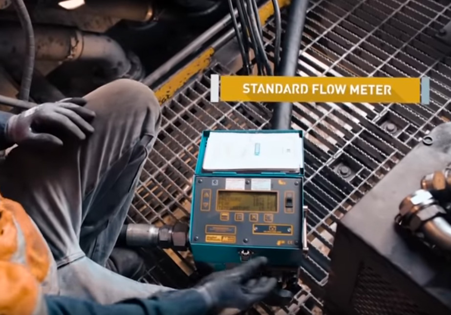
Standard Style Manual Flow Meter
The standard, industry utilised flow meter is basically as described above, a flow meter with a tap installed into the same housing. The user manually operates the tap to apply more or less restriction to flow, the resulting flow rate is then noted on a record sheet etc. Adjustments to the pump are made either straight away at the current pressure applied, or the user has to unwind the tap to reduce pressure and then make adjustments.
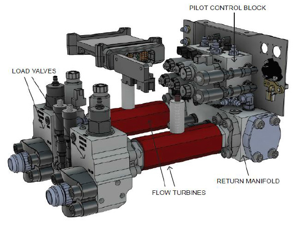
The Dual Input Flow Meter Assembly DIFMA
The Dual Input Flow Meter Assembly or DIFMA has flow turbines to measure flow similar to the manual flow meter. Where it differs is the way the flow restriction is applied and controlled. The DIFMA utilises custom designed remotely controlled valves. These valves are adjusted via a remotely located control unit. In conjunction with being able to adjust flow restriction, the technician can also remotely control all the other functions of the pump. The DIFMA is capable of connection to two pumps simultaneously.